Published: Sat 28 June 2025
By Chris Kilgour
In misc .
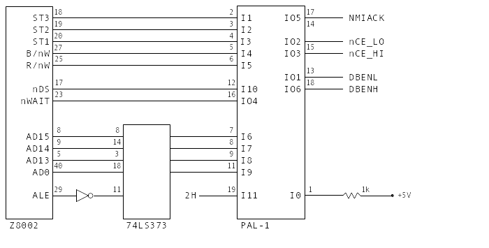
In Pole Position the Namco 51xx custom chip appears in the Option
Switch Input and I/O Interface section. Here is the portion of the
schematic redrawn.
The ID bits are a byte-wide bus coordinated by a Namco 06xx chip, the
subject of a future blog post. Here the main observation is that
these signals, and the associated handshaking, are mapped to bus
transactions of Pole Position's Z80 CPU.
Chip Operation
We know the Namco 51xx is a Fujitsu MB8843
MCU with a mask ROM.
Thanks to
Guru , we
actually have the mask ROM contents, so we can analyze the function of
the chip.
Mask ROM Analysis
The MCU's internal timer/counter is driven by VBLANK, and therefore
advances at 60 Hz. The main processing loop polls this counter, and
whenever it advances, it performs a polling sweep.
All other events are driven by the MCU's IRQ input, which is pulsed
when a 4-bit read/write command is applied by the Z80 at port K. Any
command with the MSB set causes an 8-bit value to be output at port O.
Each 8-bit value is a pair of nibbles from an internal circular buffer
of depth eight. The Z80 polls these values, also based on VBLANK.
There appears to be three 51xx operational modes, here called: IDLE
(0), INIT (1), and ACTIVE (2). These modes determine the eight-nibble
output buffer mapping. We note that the last two nibbles are never
used and always contain all bits set.
Mode
0
1
2
3
4
5
6
7
INIT
R[11:8]
R[15:12]
R[3:0]
R[7:4]
0xf
0xf
0xf
0xf
IDLE
CRED ones
CRED tens
x
x
x
x
0xf
0xf
ACTIVE
CRED ones
CRED tens
R[3:0]*
SELECT
R[7:4]*
SHIFTER
0xf
0xf
(TEST)
0xb
0xb
x
x
x
x
0xf
0xf
Note that the TEST switch is only recognized when IDLE or ACTIVE, and
the TEST mode only lasts for one VBLANK, afterwhich transitions to INIT
mode.
The * in the preceding table indicates the nibble is conditionally
subject to a lookup table mapping. The enable for this mapping is
determined by a command from the Z80.
Credit Score
Credits are maintained as Binary Coded
Decimal and
saturate at 99. TEST mode is indicated by overloading this with the
value 0xb (11) in the two digits.
Coin and credit counts are managed entirely within the 51xx MCU. When
coins are detected, any partial credits are accrued until they reach a
credit increment. Mulitple-credits per increment is also handled, if
configured. The configuration values to apply to coin and credit
counting are written to the MCU by the Z80.
The START1 signal is also handled internally. Evidently a START2
signal is also supported, but this is not connected in Pole Position.
When a START is detected, the credits are decremented and the
operational mode switches to ACTIVE. Presumably the Z80 detects this
situation by output nibbles 4 and 5 adopting a value of something
other than 0xf.
Electromechanical coin counters are pulsed in conjunction with VBLANK
count mod 16. Any pulses for COIN1 apply on VBLANK count 4, and COIN2
on VBLANK count 12. Each pulse therefore asserts for one VBLANK time,
and the two counters are presumably distributed to minimize
instantaneous current.
Miscellaneous
The 51xx outputs nibbles 0x0 and 0xf to the MCU serial port at
various times. This was not analyzed as the serial port is not
connected in Pole Position.
When the Z80 reads a byte from the 51xx, ID[2:0] are effectively
don't-care. The pattern of those bits, however, appear to change
with each read, and could be futher analyzed.
It appears a good portion of the 51xx RAM is not used.
Pseudocode
# look-up table
NIBBLE_TABLE = [ 0xf , 0xe , 0xd , 0x5 , 0xc , 0x9 , 0x7 , 0x6 ,
0xb , 0x3 , 0xa , 0x4 , 0x1 , 0x2 , 0x0 , 0x8 ]
def onReset ( ):
# all zero-inits here implied by clearing entire RAM space to zero
CREDIT_COIN_INFO = [ 0 ] * 4 # [0] = credits per coin2
# [1] = coins per credit2
# [2] = credits per coin1
# [3] = coins per credit1
OUT_NIBBLES = [ 0 , 0 , 0 , 0 , 0 , 0 , 0 , 0 ]
CREDIT_DIGITS = [ 0 , 0 ] # low, high in BCD
PARTIAL_CREDIT_COIN1 = 0
PARTIAL_CREDIT_COIN2 = 0
UNLOGGED_COIN1 = 0
UNLOGGED_COIN2 = 0
R3_DEBOUNCE = [ 0 , 0 , 0 ]
R3_STATE = 0
R2_DEBOUNCE = [ 0 , 0 , 0 ]
R2_STATE = 0
PART_CREDIT_COIN1 = 0
PART_CREDIT_COIN2 = 0
OUT_INDEX = 0
LAST_TLA = 0
DIPSW_CLEAR = False
ACTIVE_CREDITS = 0
# non-zero inits after RAM cleared
COIN_LOGGER_LINES = 0xc # active-low
R2_DEBOUNCE [ 2 ] = 0xf
R2_STATE = 0xf
OPER_MODE = 1 # "init"
def accrue_coin1 ( ):
PARTIAL_CREDIT_COIN1 += 1
if PARTIAL_CREDIT_COIN1 == CREDIT_COIN_INFO [ 3 ]:
PARTIAL_CREDIT_COIN1 = 0
CREDIT_DIGITS [ 0 ] += CREDIT_COIN_INFO [ 2 ]
if CREDIT_DIGITS [ 0 ] > 9 :
CREDIT_DIGITS [ 0 ] -= 9
CREDIT_DIGITS [ 1 ] += 1
UNLOGGED_COIN1 += 1
def accrue_coin2 ( ):
PARTIAL_CREDIT_COIN2 += 1
if PARTIAL_CREDIT_COIN2 == CREDIT_COIN_INFO [ 1 ]:
PARTIAL_CREDIT_COIN2 = 0
CREDIT_DIGITS [ 0 ] += CREDIT_COIN_INFO [ 0 ]
if CREDIT_DIGITS [ 0 ] > 9 :
CREDIT_DIGITS [ 0 ] -= 9
CREDIT_DIGITS [ 1 ] += 1
UNLOGGED_COIN2 += 1
def on_service ( ):
# increments credits without affecting coin tracking variables or loggers
CREDIT_DIGITS [ 0 ] += CREDIT_COIN_INFO [ 0 ]
if CREDIT_DIGITS [ 0 ] > 9 :
CREDIT_DIGITS [ 0 ] -= 9
CREDIT_DIGITS [ 1 ] += 1
def cache_credits ( ):
OUT_NIBBLES [ 0 ] = CREDIT_DIGITS [ 0 ]
OUT_NIBBLES [ 1 ] = CREDIT_DIGITS [ 1 ]
def onVBLANK ( ):
LAST_TLA = read_tla ( )
if OPER_MODE == 1 : # "init"
OUT_NIBBLES [ 0 ] = read_portR ( 2 ) # button/switch inputs: START1, SHIFTER, SELECT
OUT_NIBBLES [ 1 ] = read_portR ( 3 ) # button/switch inputs: TEST, SERVICE, COIN2, COIN1
OUT_NIBBLES [ 2 ] = read_portR ( 0 ) # DIP switches at 9L: LSN
OUT_NIBBLES [ 3 ] = read_portR ( 1 ) # DIP switches at 9L: MSN
OUT_NIBBLES [ 4 ] = 0xf
OUT_NIBBLES [ 5 ] = 0xf
OUT_NIBBLES [ 6 ] = 0xf
OUT_NIBBLES [ 7 ] = 0xf
else :
r3val = read_portR ( 3 )
if r3val & 8 : # TEST bit
CREDIT_DIGITS [ 0 ] = 0
CREDIT_DIGITS [ 1 ] = 0
PART_CREDIT_COIN1 = 0
PART_CREDIT_COIN2 = 0
OUT_NIBBLES [ 0 ] = 0xb
OUT_NIBBLES [ 1 ] = 0xb
OPER_MODE = 1 # "init"
write_portP ( 0xf )
else :
if CREDIT_DIGITS [ 1 ] < 10 :
R3_DEBOUNCE [ 2 ] = R3_DEBOUNCE [ 1 ]
R3_DEBOUNCE [ 1 ] = R3_DEBOUNCE [ 0 ]
R3_DEBOUNCE [ 0 ] = r3val
R3_STATE = ~ R3_DEBOUNCE [ 2 ] | R3_DEBOUNCE [ 1 ] | R3_DEBOUNCE [ 0 ]
if R3_STATE & 1 : # COIN1
accrue_coin1 ( )
if R3_STATE & 2 : # COIN2
accrue_coin2 ( )
if R3_STATE & 4 : # SERVICE
on_service ( )
cache_credits ( )
r2val = get_portR ( 2 )
R2_DEBOUNCE [ 0 ] = R2_DEBOUNCE [ 1 ]
R2_DEBOUNCE [ 1 ] = R2_DEBOUNCE [ 2 ]
R2_DEBOUNCE [ 2 ] = r2val
R2_STATE = ~ R2_DEBOUNCE [ 0 ] | R2_DEBOUNCE [ 1 ] | R2_DEBOUNCE [ 2 ]
if OPER_MODE == 0 : "idle"
if ( ACTIVE_CREDITS == 0 ) and (( CREDIT_DIGITS [ 1 ] != 0 ) or ( CREDIT_DIGITS [ 0 ] != 0 )):
tmp = 0
if ( R2_STATE & 4 ): # START1
tmp = 1
elif ( R2_STATE & 8 ): # START2 (not implemented)
tmp = 2
if tmp :
CREDIT_DIGITS [ 0 ] -= tmp
if CREDIT_DIGITS [ 0 ] < 0 :
CREDIT_DIGITS [ 0 ] += 10
CREDIT_DIGITS [ 1 ] -= 1
cache_credits ( )
OPER_MODE = 2 # "active"
PART_CREDIT_COIN1 = PART_CREDIT_COIN2 = 0
if RAMx13 == 0 :
CREDIT_DIGITS [ 0 ] = 9
CREDIT_DIGITS [ 1 ] = 10
if OPER_MODE != 0 # implies OPER_MODE==2 aka "active"
OUT_NIBBLES [ 3 ] = ( R2_STATE & 1 ) | (( R2_DEBOUNCE [ 2 ] & 1 ) << 1 ) # SELECT
OUT_NIBBLES [ 5 ] = (( R2_STATE & 2 ) >> 1 ) | ( R2_DEBOUNCE [ 2 ] & 2 ) # SHIFTER
if DIPSW_CLEAR :
OUT_NIBBLES [ 2 ] = read_portR ( 0 )
OUT_NIBBLES [ 4 ] = read_portR ( 1 )
else :
OUT_NIBBLES [ 2 ] = NIBBLE_TABLE [ read_portR ( 0 )]
OUT_NIBBLES [ 4 ] = NIBBLE_TABLE [ read_portR ( 1 )]
# 0x120
if UNLOGGED_COIN1 :
if ( read_tla ( ) == 4 ) and not ( COIN_LOGGER_LINES & 8 ):
COIN_LOGGER_LINES |= 8 # complete the logger advance COIN1
UNLOGGED_COIN1 -= 1
else :
COIN_LOGGER_LINES &= ~ 8
if UNLOGGED_COIN2 :
if ( read_tla ( ) == 12 ) and not ( COIN_LOGGER_LINES & 4 ):
COIN_LOGGER_LINES |= 4 # complete the logger advance COIN2
UNLOGGED_COIN2 -= 1
else :
COIN_LOGGER_LINES &= ~ 4
write_portP ( COIN_LOGGER_LINES )
def onIRQ ( ):
k = read_portK ( )
if k == 1 :
done = False
i = 3
while not done :
# wait for IRQ deassert and reassert
a = read_portK ( )
if a == 0 :
RAM [ 0x1a ] = 0
CREDIT_COIN_INFO [ i -- ] = a
done = ( i < 0 )
elif k == 2 :
OPER_MODE = 0 # "idle"
elif k == 3 :
DIPSW_CLEAR = True
elif k == 4 :
DIPSW_CLEAR = False
elif k == 5 :
OPER_MODE = 1 # "init"
elif k <= 7 :
pass # do nothing
else : # k >= 8
write_portO ( 0 , OUT_NIBBLES [ OUT_INDEX ++ ])
write_portO ( 1 , OUT_NIBBLES [ OUT_INDEX ++ ])
if OUT_INDEX >= 8 :
OUT_INDEX = 0
def main ( ):
onReset ( )
onVBLANK ( )
while True :
tla = read_tla ( )
if LAST_TLA != tla :
onVBLANK ( )