
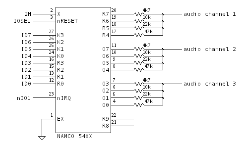
In Pole Position the Namco 54xx custom chip appears in the Miscellaneous Sound Generators section. Here is the portion of the schematic redrawn.
Chip Operation
We know the Namco 54xx is a Fujitsu MB8844 MCU with a mask ROM. Thanks to Guru, we actually have the ROM contents, so we can analyze the function of the chip.
Mask ROM Analysis
A disassembly of the Namco 54xx mask ROM reveals the following operation (pseudocode).
Three audio channels are developed, with their outputs determined by a master linear feedback shift register, and with independent amplitude envelopes.
def main( ):
    clearRAM( ) # variables in ALL_CAPS are in RAM, initialized to zero

    while True:
        advanceLFSR( )
        handleChannelA( )
        handleChannelB( )
        handleChannelC( )

def advanceLFSR( ):
    b2   = (LFSR >>  2) & 1
    b13  = (LFSR >> 13) & 1
    b16  = b2 ^ b13 ^ 1
    LFSR = (b16 << 16) | ((LFSR >> 1) & 0xffff)

def handleChannelA( ):
    STATE_A = LFSR & 1
    OUT_AMPLITUDE_A = (0, AMPLITUDE_A)[STATE_A]

    if DOWNCOUNT_A & 0xf000:
        if (DOWNCOUNT_A & 0xfff) == 0:
            nextState = ((DOWNCOUNT_A >> 12) & 3) - 1
            if nextState == 2: # attack->decay
                AMPLITUDE_A = 0
                DOWNCOUNT_A = 0x2000 + (DECAY_DURATION_A << 4)
            elif nextState == 1: # decay->sustain
                AMPLITUDE_A = SUSTAIN_AMPLITUDE_A
                DOWNCOUNT_A = 0x1000 + (SUSTAIN_DURATION_A << 4)
            else: # releasing
                AMPLITUDE_A = AMPLITUDE_A * 3 / 4
                DOWNCOUNT_A = 0x1fff
        else:
            DOWNCOUNT_A -= 1

def handleChannelB( ):
    STATE_B ^= (0, 1)[bool(LFSR & 3 == 1)]
    OUT_AMPLITUDE_B = (0, AMPLITUDE_B)[STATE_B]

    if DOWNCOUNT_B & 0xf000:
        if (DOWNCOUNT_B & 0xfff) == 0:
            nextState = ((DOWNCOUNT_B >> 12) & 3) - 1
            if nextState == 2: # attack->decay
                AMPLITUDE_B = 0
                DOWNCOUNT_B = 0x2000 + (DECAY_DURATION_B << 4)
            elif nextState == 1: # decay->sustain
                AMPLITUDE_B = SUSTAIN_AMPLITUDE_B
                DOWNCOUNT_B = 0x1000 + (SUSTAIN_DURATION_B << 4)
            else: # releasing
                AMPLITUDE_B = AMPLITUDE_B * 3 / 4
                DOWNCOUNT_B = 0x1fff
        else:
            DOWNCOUNT_B -= 1

def handleChannelC( ):
    STATE_C += BASE_INCREMENT_C
    if LFSR & 1:
        STATE_C += SUPPLEMENTAL_INCREMENT_C
    OUT_AMPLITUDE_C = (0, AMPLITUDE_C)[(STATE_C >> 7) & 1]

    if DOWNCOUNT_C & 0xf000:
        if (DOWNCOUNT_C & 0xfff) == 0:
            nextState = ((DOWNCOUNT_C >> 12) & 3) - 1
            if nextState == 1: attack->sustain
                if SUSTAIN_DURATION_C == 0: # hard release
                    DOWNCOUNT_C = 0
                    AMPLITUDE_C = 0
                else: # establish sustain time
                    DOWNCOUNT_C = 0x1000 + (SUSTAIN_DURATION_C << 4)
            else: # releasing
                AMPLITUDE_C = AMPLITUDE_C * 3 / 4
                DOWNCOUNT_C = 0x1fff

def onExternalInterrupt( ):
    storeBytes = 0
    storeAddr  = 0
    command = PORTK
    if command == 1:
        AMPLITUDE_A = ATTACK_AMPLITUDE_A
        DOWNCOUNT_A = 0x3000 + (ATTACK_DURATION_A << 4)
    elif command == 2:
        AMPLITUDE_B = ATTACK_AMPLITUDE_B
        DOWNCOUNT_B = 0x3000 + (ATTACK_DURATION_B << 4)
    elif command == 3:
        storeBytes = 4
        storeAddr  = 0x37 # pointer for parameters for channel A
    elif command == 4:
        storeBytes = 4
        storeAddr  = 0x3f # pointer for parameters for channel B
    elif command == 5:
        AMPLITUDE_C = ATTACK_AMPLITUDE_C
        DOWNCOUNT_C = 0x2000 + ATTACK_DURATION_C
    elif command == 6:
        storeBytes = 5
        storeAddr  = 0x29 # pointer for parameters for channel C
    elif command == 7:
        AMPLITUDE_C = PORTR0

    while storeBytes:
        waitForEIRQ( )
        RAM[storeAddr]   = PORTR0
        RAM[storeAddr-1] = PORTK
        storeBytes -= 1
        storeAddr  -= 2
Channel Enumeration
Pole Position enumerates the output channels as 1, 2, and 3. However, it's evident from the mask ROM disassembly, and the MAME sources, that those are reverse to the order of implementation. In this article we use the channels A, B, and C, which correspond to Pole Position channels 3, 2, and 1 respectively.
Linear Feedback Shift Register
A 17-bit LFSR is implemented as shown below.
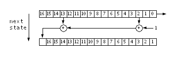
After an initial startup sequence of (hex):
- 00000h
- 10000h
- 18000h
The register advances through 32767 states and loops around to state 18000h again. This effectively implements a 15-bit maximal-length LFSR that avoids the all-zero lock state.
The least-signifcant bit of the shift register is presented at output pin R8.
Envelope Control
The main loop advances through independent state machines controlling the amplitude-level envelope for each of the three output channels. Roughly speaking, these correspond to the well-known ADSR model.
A channel's envelope state machine primarily based on a 14-bit down counter. The two most-significant bits determine the state of the ADSR-like envelope, with state corresponding to (for example) 3=A, 2=D, 1=S, and 0=R. Each envelope counter is decremented once per operational loop (once per advance of the LFSR).
Command Interface
The Namco 54xx MCU accepts 8-bit writes from an external master (in Pole Position, the Z80 sound CPU). The most-signifiant nibble of the the intial byte is treated as a command value, and the least-significant nibble is ignored for all but command 7.
Acceptance of the command byte is handled via interrupt, which naturally introduces delays in the main loop processing. Presumably Namco did this on purpose, since the short interruptions to the LFSR and envelope updates are likely not noticeable to the gamer, and perhaps might even enhance the random character of the generated noise.
Some command bytes cause the MCU to accept subsequent bytes as arguments. These bytes are accrued in a polled mode while still in the interrupt handler.
| Command MS Nibble | Additional Bytes | Result |
|---|---|---|
| 0x0, 0x8-0xf | 0 | Ignored |
| 0x1 | 0 | Start sound A |
| 0x2 | 0 | Start sound B |
| 0x3 | 4 | Configure sound A |
| 0x4 | 4 | Configure sound B |
| 0x5 | 0 | Start sound C |
| 0x6 | 5 | Configure sound C |
| 0x7 | 0 | Configure sound C amplitude with LS nibble |
Loop Timing
The LFSR and envelope state machines update within the free-running main loop with a varying loop time (depending on conditionals, and interrupts) of at least 90 cycles. On Pole Position, the MCU clock is 24.576 / 8 = 1.536 MHz. Since the MCU has six internal phases per opcode, the instruction tick rate is 256 kHz. That makes a 90-cycle update loop generate noise at 2844 sps. An audio clip of the full length of the LFSR therefore takes 11.5 seconds.
Here is a single cycle of the LFSR generated at half-amplitude.
The fundamental timing unit of the envelope state machines runs at this loop rate. Roughly speaking, to accommodate varying code paths due to conditionals, we estimate the operational loop at 128 opcode cycles. That means 2000 loops per second, so approximately 1/2 ms per down-counter decrement. The maximum duration of any envelope state is therefore about 2000ms (2^11 ms).
Audio Channel A (Pole Position Channel 3)
Whenever the LFSR output is one, then a 4-bit value from RAM 0x15 is presented to audio output A. This amplitude level is initially zero at MCU reset, resulting in silence, but is updated by the operation of the envelope state machine.
Envelope Control
For channel A, the least significant nibble of the 14-bit down counter is treated as a /16 prescaler, and maintained in RAM nibble 0x08. At the prescale rate, the right-justified 10-bit value in RAM 0x18:0x17:0x16 is decremented. The most-significant nibble of this value, in RAM location 0x18, determines the state of the channel A envelope.
The counter is initialized when command 1 is written to the MCU. This causes RAM 0x18 to be initialized with the value 3, RAM 0x17:0x16 to be initialized from RAM 0x37:0x36, and the amplitude level at RAM 0x15 to be initialized from RAM 0x30. This is similar the ADSR attack phase, except it is an amplitude step, and sustains until the 14-bit down counter decrements to 3:0:0:0.
On the next tick, as the counter decrements to 2:f:f:f, the middle eight bits are updated with RAM 0x35:0x34, and the amplitude is set to zero. This is similar to the ADSR decay phase, except the decay is instantaneous and has zero amplitude, and lasts until the counter decrements to 2:0:0:0.
As the 14-bit down counter decrements to 1:f:f:f, the middle eight bits are updated with RAM 0x33:0x32, and the amplitude is set to RAM 0x31. This is the ADSR sustain phase and lasts until the counter reaches 1:0:0:0.
On the next tick, as the counter decrements to 0:f:f:f, the audio starts fading by selecting 3/4 of its current value, and the counter is set to 1:f:f:f. This is the ADSR release phase. Once the audio fades to 0, RAM 0x18 is left at zero and the envelope is complete.
Parameter Summary (Command 3)
| Byte/Nibble | RAM | Content |
|---|---|---|
| 3 MSN | 0x30 | Attack amplitude |
| 3 LSN | 0x31 | Sustain amplitude |
| 2 MSN | 0x32 | Sustain duration LS |
| 2 LSN | 0x33 | Sustain duration MS |
| 1 MSN | 0x34 | "Decay" duration LS |
| 1 LSN | 0x35 | "Decay" duration MS |
| 0 MSN | 0x36 | Attack duration LS |
| 0 LSN | 0x37 | Attack duration MS |
Audio Channel B (Pole Position Channel 2)
Audio channel B operates the same as audio channel A except its instantaneous state is derived differently from the LFSR. Whenever the most recent two output bits of the LFSR is 01b, the output state is toggled. The bit pattern appears on output pin R9.
The envelope applied to audio channel B is the same as channel A, but with independent parameters. The envelope is started with command 2.
Parameter Summary (Command 4)
| Byte/Nibble | RAM | Content |
|---|---|---|
| 3 MSN | 0x38 | Attack amplitude |
| 3 LSN | 0x39 | Sustain amplitude |
| 2 MSN | 0x3a | Sustain duration LS |
| 2 LSN | 0x3b | Sustain duration MS |
| 1 MSN | 0x3c | "Decay" duration LS |
| 1 LSN | 0x3d | "Decay" duration MS |
| 0 MSN | 0x3e | Attack duration LS |
| 0 LSN | 0x3f | Attack duration MS |
Audio Channel C (Pole Position Channel 1)
The output for audio channel C is derived from the LFSR, but differently from both channel A and channel B. The LFSR application amounts to random frequency modulation, with programmable deviation of a (also programmable) base tone.
An 8-bit value is maintained in RAM nibbles 0x2b:0x2a, and updated every loop (ie. every LFSR update). On each loop, a base value from RAM nibbles 0x29:0x28 is added. If the LFSR output is set, then a supplemental value from RAM nibbles 0x28:0x27 is also added. The audio output is determined by the most-significant bit of this 8-bit value (ie. bit 3 of RAM nibble 0x2b). This is the core operation of (base) tone generation with random frequency deviation.
Automatic Envelope Control
Rather than operating like channels A and B, channel C's envelope implements only three states. Similar to the other channels, it relies on the 14-bit down counter to trigger the state change. We call these states ASR, where A=2, S=1, and R=0.
The 14-bit down counter is maintained, right-justified, in RAM nibbles 0x1f:0x2e:0x2d:0x2c. Nibble 0x1f is the envelope state variable.
The counter is initialized when command 5 is written to the MCU. This causes RAM nibble 0x1f to be set to 2, and the remaining bits to be initialized from RAM nibbles 0x23:0x22:0x21. At the same time, the output amplitude, maintained in RAM nibble 0x2f, is initialized to the value in RAM nibble 0x20. This is the attack phase, and lasts until the 14-bit down counter decrements to 2:0:0:0.
On the next tick, as the counter decrements to 1:f:f:f, the middle eight bits are updated with the contents of RAM nibbles 0x25:0x24, and the least significant is set to zero. This is the sustain phase, and lasts until the 14-bit down counter decrements to 1:0:0:0.
Note that in the special case when the configured sustain time at 0x25:0x24 is zero, the sustain phase is skipped. The output amplitude is set to zero as is the state variable in nibble 0x2f.
The end of any sustain phase continues with the next tick, as the counter decrements to 0:f:f:f. While in state 0, the output amplitude decays the same as channels A and B (By taking on 3/4 of it's current value at each tick). Once the value to zero, audio output holds there.
The output level and timer value are parameters provided as follows.
Parameter Summary (Command 6)
| Byte/Nibble | RAM | Content |
|---|---|---|
| 4 MSN | 0x20 | Attack amplitude |
| 4 LSN | 0x21 | Attack duration b3:0 |
| 3 MSN | 0x22 | Attack duration b7:4 |
| 3 LSN | 0x23 | Attack duration b11:8 |
| 2 MSN | 0x24 | Sustain duration LS |
| 2 LSN | 0x25 | Sustain duration MS |
| 1 MSN | 0x26 | Supplemental increment LS |
| 1 LSN | 0x27 | Supplemental increment MS |
| 0 MSN | 0x28 | Base increment LS |
| 0 LSN | 0x29 | Base increment MS |
External Envelope Control
The MCU command master may perform arbitrary envelope control by manipulating the amplitude of audio channel C directly. This is accomplished with command 7.
Application In Pole Position
Here is a follow-on article on how this Namco 54xx noise generator chip is used in Pole Position.