
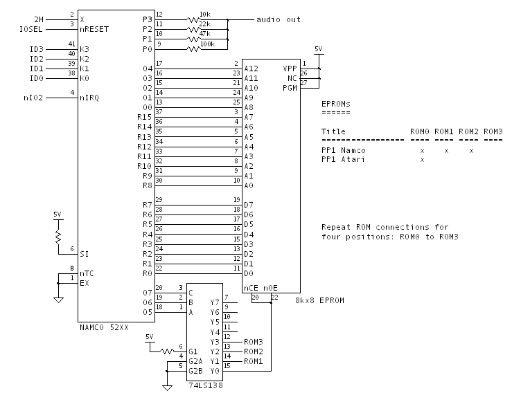
In Pole Position the Namco 52xx custom chip appears in the Speech Processor and Memory section. Here is the portion of the schematic redrawn.
Chip Operation
We know the Namco 52xx is a Fujitsu MB8843 MCU with a mask ROM. Thanks to Guru, we actually have the mask ROM contents, so we can analyze the function of the chip.
Mask ROM Analysis
A disassembly of the Namco 52xx mask ROM reveals the following operation (pseudocode).
The MCU uses its internal timer interrupt to coordinate the delivery of 4-bit audio samples to port P. Two 4-bit audio samples are held in memory for the interrupt handler to deliver in sequence. The audio samples are copied from the sample ROMs, one byte at a time, whenever the two buffered audio samples are cleared out by the interrupt handler. The entire sequence of samples is determined by address ranges held in a table at the beginning of the sample ROM. A 4-bit nonzero value written to port K (i.e. by the Z80 in Pole Position, look for articles on this one later) selects the index into the table and kicks off playback.
def onReset( ):
    SAMPLE_NIBBLE_BUF = [8, 8]
    SAMPLE_INDEX      = 0
    ACTIVE_CLIP       = 0
    SAMPLE_ADDRESS    = 0x0020

    timer_clock_internal = (READ(SAMPLE_ADDRESS) >> 4) == 0xf
    enableTimerAndInterrupt(timer_clock_internal)
    TIMER_VAL = 0xfe # -2, timer will roll-over and interrupt in 2 ticks

def onTimerInterrupt( ):
    TIMER_VAL = 0xfe # -2, timer will roll-over and interrupt in 2 ticks
    OUTP = SAMPLE_NIBBLE_BUF[SAMPLE_INDEX]
    if SAMPLE_INDEX < 2:
        SAMPLE_INDEX += 1

def acceptAndActivateClip( ):
    ACTIVE_CLIP      = PORTK
    CURRENT_ADDRESS  = READ(0x0000 + (ACTIVE_CLIP - 1))
    CURRENT_ADDRESS |= READ(0x0010 + (ACTIVE_CLIP - 1)) << 8
    END_ADDRESS      = READ(0x0000 + (ACTIVE_CLIP))
    END_ADDRESS     |= READ(0x0010 + (ACTIVE_CLIP)) << 8

def main( ):
    onReset( )

    while True:
        # poll EIRQ (write signal) and port K, accept non-zero clip number
        while not EIRQ or (PORTK == 0):
            continue

        acceptAndActivateClip( )

        while CURRENT_ADDRESS != END_ADDRESS:
            SAMPLE_ADDRESS = CURRENT_ADDRESS
            # wait for current samples to clock out via interrupt
            while SAMPLE_INDEX != 2:
                continue

            # queue up next two 4-bit samples
            SAMPLE_NIBBLE_BUF = READ(SAMPLE_ADDRESS) # least-significant nibble first

            # allow a higher-value clip to override
            if EIRQ and (PORTK > ACTIVE_CLIP):
                acceptAndActivateClip( )
            else:
                CURRENT_ADDRESS += 1
Sample ROM Header Contents
If we consider the first 32 bytes of sample ROM to be 16 columns of two bytes each, the start and end address for clip N is held in the N-1 and Nth columns, respectively.
We also note that an extra byte of header is used to signify whether the Namco 52xx uses an internal or external clock for timing. Internal timing is used when the most-significant nibble is 0xf, which is the case for Pole Position.
Stop Address Bug
It's evident from the MCU disassembly that the sample playback termination address is not stored correctly. Although the least-significant nibble of the end address is read from the clip table, it is not stored into the RAM location used for playback termination. That leaves the playback address incorrect by up to 15 bytes, resulting in up to 30 extra samples, or 30 too few samples, being played back.
Here is the code that sets up the current and end addresses for sample playback. The error is a missing 'ST' instruction between MCU code addresses 0xa1 and 0xa2.
; ACC holds the selected clip value
; Set up address and read the clip start address from sample ROM into RAM nibbles 6..9
06c: 83   : LYI #3
06d: 07   : TAS
06e: 1a   : STDC
06f: 7f   : AI #15
070: 23   : RSTC
071: 03   : OUT                         ; [A3:A0] <= (clip - 1)
072: 90   : LI #0
073: 83   : LYI #3
074: 03   : OUT                         ; [A7:A4] <= 0x0
075: 01   : OUTO                        ; [A11:A8] <= 0x00
076: 9e   : LI #14
077: 54   : XYD #4
078: af   : CYI #15
079: fb   : JMP 0x07b
07a: 90   : LI #0
07b: 54   : XYD #4
07c: 21   : SETC
07d: 01   : OUTO                        ; [A15:A12] <= 0x00
07e: 80   : LYI #0
07f: 13   : IN
080: 86   : LYI #6
081: 1d   : ST                          ; save [D3:D0] in RAM nibble 6
082: 81   : LYI #1
083: 13   : IN
084: 87   : LYI #7
085: 1d   : ST                          ; save [D7:D4] in RAM nibble 7
086: 83   : LYI #3
087: 91   : LI #1
088: 03   : OUT                         ; [A7:A4] <= 0x1
089: 80   : LYI #0
08a: 13   : IN
08b: 88   : LYI #8
08c: 1d   : ST                          ; save [D3:D0] in RAM nibble 8
08d: 81   : LYI #1
08e: 13   : IN
08f: 89   : LYI #9
090: 1d   : ST                          ; save [D7:D4] in RAM nibble 9
; Set up address and read the clip end address from sample ROM into RAM nibbles 10..13
091: 82   : LYI #2
092: 17   : TSA
093: 03   : OUT                         ; [A3:A0] <= clip
094: 80   : LYI #0
095: 13   : IN
096: 8c   : LYI #12
097: 1d   : ST                          ; save [D3:D0] in RAM nibble 12
098: 81   : LYI #1
099: 13   : IN
09a: 8d   : LYI #13
09b: 1d   : ST                          ; save [D7:D4] in RAM nibble 13
09c: 83   : LYI #3
09d: 90   : LI #0
09e: 03   : OUT                         ; [A7:A4] <= 0x00
09f: 80   : LYI #0
0a0: 13   : IN                          ; read [D3:D0]
0a1: 8a   : LYI #10
                                        ; but fail to save value in RAM nibble 10
0a2: 81   : LYI #1
0a3: 13   : IN
0a4: 8b   : LYI #11
0a5: 1d   : ST                          ; save [D7:D4] in RAM nibble 11
0a6: 68 ff: JPL 0x0ff
Inspecting The Atari Clip Table
Now we turn out attention to the clip table in Pole Position.
$ od -tx1 -Ax -N33 136014.106
000000 00 04 1a 1a 00 00 00 00 00 00 00 00 00 00 00 00
000010 00 0c 1c 46 00 00 00 00 00 00 00 00 00 00 00 00
000020 f0
We can see from the first 33 bytes of the sample ROMs that there are three different sound clips.
Correcting Audio Clip Limits
The first sound clip lists the starting address as 0x0000, which is clearly not correct given the first 33 bytes of the sample ROM are not audio samples but rather header data. If we correct for this error we find:
Clip #1: 6086 samples, 0x0021 to 0x0c04
Clip #2: 8236 samples, 0x0c04 to 0x1c1a
Clip #3: 21504 samples, 0x1c1a to 0x461a
Note that the Namco Japanese sample ROMs do have the correct starting address for clip #1 (0x0021). Perhaps Namco/Atari fouled up when they cooked up the English audio.
Clip 3 Oddness
On the Atari Pole Position, only one sample ROM is populated (ROM0 on diagram). So no audio samples exist beyond address 0x1fff. However, Atari did not modify the contents of the clip table in the Namco ROM0 header to correct the termination address of clip 3. It will continue to playback samples all the way until address 0x461a, reading 0xff for each byte between 0x2000 and 0x461a.
It's also notable that with three 8k sample ROMs, space is available in the Namco Pole Position for sound samples through to 0x5fff. Although there is no clip table entry for this data, we can still try listening to it as a clip.
Recovering The Audio
Audio Output Levels
If we want to listen to the data, it would be most convenient to use 8-bit samples. The resistor ladder output is analyzed with a simple Python program, whose output is:
     Voltage    As Byte
     =======    =======
0x0: 0.000V --> 0x00
0x1: 0.283V --> 0x0e
0x2: 0.602V --> 0x1e
0x3: 0.885V --> 0x2d
0x4: 1.286V --> 0x41
0x5: 1.569V --> 0x50
0x6: 1.888V --> 0x60
0x7: 2.171V --> 0x6f
0x8: 2.829V --> 0x90
0x9: 3.112V --> 0x9f
0xa: 3.431V --> 0xaf
0xb: 3.714V --> 0xbe
0xc: 4.115V --> 0xd2
0xd: 4.398V --> 0xe1
0xe: 4.717V --> 0xf1
0xf: 5.000V --> 0xff
Conversion to WAV
Python sure makes it easy to generate WAV files, but we need 8-bit samples and need to know the sampling rate. I haven't analyzed the MB884x timer operation closely enough to know exactly what sampling rate the Namco 52xx uses, so I just guessed 4000 sps.
Here are the results: